 |
| Today Idlib is under a murderous assault by Assad & Putin |
Once I decided that this document merits serious attention, the first thing I did was run it through my favorite Open Source Software Optical Character Reader (OCR) so that I could have a text copy to work with. So now, in the spirit of open source, I want to make that work product available to the world, even though I believe this document is being used by supporters of war criminals to attack the chemical police, and normalize the use of chemical weapons in the twenty-first century.
The group that originally posted it to the Internet, the Working Group on Syria, Propaganda and Media claimed that they were communicating with unnamed "OPCW staff members." In posting it, they said:
A copy of a 15-page Executive Summary of this report with the title “Engineering Assessment of two cylinders observed at the Douma incident” has been passed to us and we have posted it here. Please download and share this document via your own server if you link to it, so as not to overload our server.So, you see, what I am doing here is very much in the spirit of their request. Not only am I sharing this document on Google's dime, I'm making it even more accessible by making its contents searchable within a text editor, and once the search engines pick up this blog, on the Internet as well.
That it was "leaked" in this inaccessible form raises some troubling questions. Did they not have access to a document format version of this document? If so, why did they publish it in such a limited image format?
Directly following the statement above they say:
We are studying this document, and encourage others with relevant expertise to contribute.It's hard to understand how they have been studying this document, or expect "experts" to study it, when they can't even cut and paste from it. If they didn't receive it in a document format, they'd need to convert it to one before it could be studied serious. Now, I have saved them the trouble. They should thank me.
If they have only received what they have forwarded to us, and they have had no contact with Ian Henderson, how do they know the document is genuine? Contrary to the stories they tell, the OPCW has not validated this document. The OPCW said they didn't release it, and they are looking into it.
A document in electronic format can be subjected to checksum tests to insure that it hasn't been modified, and it can even be signed with a digital signature that could give us a high level of assurance about who produced it. None of that is possible with what we have, not the document itself, but a scanned image copy of the document. It's child's play to modify and scan a paper copy. All that it requires is a little cut and paste the old fashion way. If that's all the Working Group received, they are taking it on faith that it is genuine in any sense because they can't even verify that it hasn't been modified since Henderson produced it.
Clay Claiborne, Linux Systems Administer L2
On the “leaked” Henderson report, see also:
Lies, damned lies, and engineering sub-team reports
Where in the world is Ian Henderson?
More on the silent Ian Henderson and his "leaked" OPCW paper
Dr. Ted Postol rides again - right into the OPCW "leak" controversy
OPCW Word Games - Exposing the Politics of the Henderson "leak"
If you find any errors or typos in the document, please note them in the comment section and I will fix them, that being said, here it is:

UNCLASSIFIED - OPCW Sensitive
Do not circulate
- Executive Summary
DRAFT FOR INTERNAL REVIEW
Expanded Rev 1 — 27 February 2019
1. This note relates to the incident of alleged use of toxic chemicals as a weapon in Douma on 7 April 2018 in the Syrian Arab Republic.
2. As part of the fact-finding mission, information was gathered and assessed on two chlorine cylinders, observed at two separate locations in Douma. The FFM team visited both these locations:
- Location 2, where it observed the presence of an industrial gas cylinder on a top floor patio/terrace of an apartment block, next to a crater-like opening in the reinforced concrete roof leading to a room below.
- Location 4, where it observed the presence of a similar cylinder lying on a bed in a top floor room of an apartment, with a crater-like opening in the reinforced concrete roof above the room.
3. An engineering assessment has been conducted, using all available information, to evaluate the possible means by which these two cylinders arrived at their respective locations as observed. This report summarises the findings of the engineering sub—team.
Approach
4. The studies on the two cylinders were conducted using sources of information available to the FFM team, which included: open—source material (images and videos); observations and measurements taken by the FFM team at both locations; photographs taken by the FFM team at both locations; and engineering data from open—source information relating to the dimensions, design code, specifications, materials of construction and mechanical properties of the cylinders, sourced from the manufacturer's stamps and country of manufacture. -
5. Samples were taken by the FFM team at both locations. Whilst the results of analysis are obviously relevant for the overall investigation of the alleged incident, they were not the central focus in the scope of this element of the fact—finding mission. It was necessary, however, to make some assumptions; for example, about the likely contents of the cylinders, in order to provide inputs for the engineering assessment. These were necessarily defined as scenarios to be used in the development of hypotheses, as described below.
Hypotheses
6. To derive the inputs for an engineering assessment, it was necessary to develop hypotheses for what was thought (i.e. alleged) to have occurred. This needed to be done in a way that did not pre-judge the situation or lead prematurely to a mistaken interpretation of the facts. The situation was also complicated by the many sources of information and opinion about what was alleged to have
Page 1 of 15
UNCLASSIFIED - OPCW Sensitive
Do not circulate
occurred, including impressions and views of alleged witnesses, spokespersons, the media, representatives of States Parties, as well as the views of supposed experts in subsequent exchanges.
7. Keeping the above in mind, an attempt was made to define a set of assumptions and at least two clear opposing hypotheses for each of the two locations, to use as inputs for the baseline cylinder studies. The baseline studies were aimed at examining the two situations in terms of what is alleged to have happened in each case, as best as is currently understood. This was then tested against an alternative explanation. This methodology will be expanded if any new facts or information need to be ta ken into account.
8. Location 2 Hypotheses
- Hypothesis L2-1: The observed object was of a standard design for a cylinder used for storage of liquefied chlorine. The cylinder, full or partly full of liquefied chlorine, was dropped from an aircraft (most likely a helicopter) from an unknown altitude, and fell onto the reinforced concrete roof of the terrace. The cylinder built up velocity during the free fall and the resulting impact pierced the roof, forming the crater that was observed in the roof. The impact resulted in fracture of the valve at the front of the cylinder, thus discharging the contents (the cylinder was found by the FFM team to be empty), and caused structural deformation of the cylinder itself. Other observations may have had influences in this hypothesis, i.e. the cylinder may have been fitted with a crude mild steel framework and fins (remnants of these were observed on the terrace) and the terrace may have been covered with an angle-iron frame and wire netting cover.
- Hypothesis L2-2: The observed object is of a standard design for a cylinder used for storage of liquefied chIorine. The cylinder, full 'or' partly full of liquefied chlorine, orwempty, was in the possession of persons who placed it on the terrace next to a pre-existing crater.
9. Location 4 Hypotheses
- Hypothesis L4-1: The observed object was of a standard design for a cylinder used for storage of liquefied chlorine, and was fitted with a crude mild steel framework and fins. The cylinder, mostly full of liquefied chlorine, was dropped from an aircraft (most likely a helicopter) from an unknown altitude, and fell onto the reinforced concrete roof of the bedroom. The cylinder built up velocity during the freefall and the resulting impact pierced the roof, forming the crater that was observed in the roof. The cylinder penetrated through the crater and was subsequently deflected laterally to end up on the bed in the room, in the position observed by the FFM team and shown in open-source images. The valve remained intact and the cylinder contents remained within the vessel.
- Hypothesis L4-2: As for L4-1, but with the possibility that the cylinder had landed on the floor of the room underneath the crater, and had subsequently been picked up and placed on the bed by the first persons at the scene. There is no particular persuasion for this, or reason to believe that it occurred, but it may be best to acknowledge it as a possibility.
- Hypothesis L4-3: The observed object is of a standard design for a cylinder used for storage of liquefied chlorine, and was fitted with a crude mild steel framework and fins. The deformed
Page 2 of 15
UNCLASSIFIED - OPCW Sensitive
Do not circulate
cylinder, mostly full of liquefied chlorine, was in the possession of persons who placed it on the bed in the bedroom. The crater in the roof was created (by unspecified means) either prior to or after the cylinder was placed on the bed.
Methodology — Location 2 study
10. The key observations at Location 2 were the cylinder, which showed a specific mode and extent of deformation, and the crater. Critical elements of this study were identified as (1) cylinder deformation, (2) the size, shape and characteristics of the crater, and (3) a relative comparison of the cylinder and crater, i.e. was there the match of an assumed impact between the two?
The study focussed on two main considerations; kinetic energy dissipation through plastic deformation of the cylinder, and through mechanical damage to the reinforced concrete plate (the concrete slab). It was decided to perform an engineering assessment of the coupled and uncoupled mechanical responses to the alleged impact.
11. In a first step the mechanical responses of the vessel and the concrete plate were uncoupled, i.e. the impact of the vessel on a rigid plate and the impact of a rigid body (with the geometry of the contact surface of the vessel) on a concrete target were studied separately. Consequently, in the first case, the total kinetic energy of the vessel had to be absorbed completely by the vessel itself, mainly by plastic deformation of the vessel material. In the second case, only the concrete plate would dissipate energy and slow down the rigid mass. This step was required to fine-tune the material model adopted for the concrete. The results clearly showed that both the vessel deformation and concrete crater of the observed impact event could not be caused by a perfectly vertical impact. An impact angle of approximately 20° was found to be required for results to bear any resemblance to observations. The simulation results, however, also showed that the defamation of the vessel and the penetration of the concrete plate cannot be
uncoupled, as there was a strong mutual interaction.
12. Therefore, in the next step, the impact of the vessel on a deformable concrete target was studied. For this impact case, vessel and concrete plate both absorb'energy. Next to providing insight into the relation between certain impact conditions and the resulting deformation and damage patterns, the simulations were also intended to address the question as to whether a vessel, dropped from an assumed height (a range of heights was tested, resulting in calculated impact velocities), gave rise to deformation and damage patterns similar to the ones observed in the images of the vessel/plate impact case shown in numerous images of the alleged incident. Further analysis of the results of the simulated cases focussed on the following:
- deformation geometry of the vessel and how the vessel shape evolved during the deceleration process;
- deformation and, if considered, damage pattern of the concrete plate; and
- evolution of the velocity of the vessel from its initial value until the end of the impact event.
13. Following this, the scope of the study was expanded to account for the influence of the steel reinforcing bars in the concrete slab. This required further consultation with concrete modelling
Page 3 of 15
UNCLASSIFIED - OPCW Sensitive
Do not circulate
experts to establish the rigorous integrated model which took into account all three mechanisms, i.e. vessel deformation, concrete defamation and damage, and deformation and damage on the rebar within the concrete slab. Commercial finite element code Abaqus/Explicit was used as the modelling platform.
14. In addition, expert assessment was provided on the appearance of the upper and underneath surfaces of the crater and surrounding walls and debris, by examination of multiple photographs of the scene.
15. After the simulations were run, results were compared with the actual observed deformation of the cylinder observed at Location 2. Additionally, both the simulation results and obsenled cylinder defamation were compared with images of previously-observed deformed cylinders from similar alleged incidents from 2014 to 2017, noting that in most cases these cylinders were reported to have landed on a supported concrete substrate (i.e. with soil or aggregate underneath).
Methodology — Location 4 study
16. An assessment of the situation at Location 4 prompted a different approach. According to hypothesis L4-1 the cylinder would have landed on the concrete roof, suffered deformation (along with the associated steel frame, wheels and fins) through impact and subsequent travel through the resultant crater, and landed on the bed. The appearance of the cylinder was apparently consistent with such an object having suffered a flat/horizontal impact with a horizontal surface; however the relative appearance of the cylinder and crater, the penetration through the crater, and the lateral movement of the cylinder post-impact within the room needed further analysis.
It was decided as a first stage to perform a scaled dimensional analysis of the scene at the incident, using images (taken by the FFM team), site observations and measurements, and subsequent reconstruction of the scene using scaled dimensions derived from photographs that included the scale of a tape measure. The study included the following elements:
- Measurements were taken at the scene, and photographs (some including tape measure reference scales) were taken of the crater from the roof of the building. These were used to establish an accurate scale drawing of the crater.
- Measurements, observations and photographs were taken inside the room; of the crater in the roof, the cylinder, walls, and objects of furniture and fittings within the room. These were used to establish a scale drawing of the deformed cylinder, to reconstruct pre-deformation cylinder dimensions, with un-deformed frame and fins, and to create a scale drawings of these taking into account that (in addition to deformation) the framework appeared to have been displaced backwards as a result of an impact.
- A scaled 3-D model was generated of the pre-deformation cylinder and the crater, in order to examine the range of possible configurations upon impact, and predicted damage and deformation caused by subsequent travel through the crater.
- An assessment was performed on the possible dynamics of the lateral movement (post-entry) of the cylinder within the room, examining the three mechanisms considered feasible; (1) incoming
Page 4 of 15
UNCLASSIFIED - OPCW Sensitive
Do not circulate
flight trajectory, (2) deflection off walls or objects in the room, and (3) transferred floor friction by a ”compressive-restitution” effect resulting from plastic deformation of the cylinder due to impact and subsequent recovery due to internal pressure (comparable with an ovoid compression-restitution model, the mechanism for altering direction in a bounce, the so—called ”rugby ball effect”).
Findings - Location 2
17. For the final simulations, a realistic damage model was adopted for the concrete, initially without steel reinforcement. Using the model under aforementioned assumptions, regardless of the inclination angle and initial velocity considered, the vessel not only fully penetrated the concrete plate, but still had a non-negligible velocity after penetration. Analysis of the evolution of the vessel deformation during the penetration of the concrete showed that the vessel shape observed in the observed (alleged impact) event could only have been caused by an impact, under an angle of 20°, with an initial velocity significantly lower than the ones considered in the simulations.
18. Based on these results, an initial part of the study was narrowed to establishing whether a concrete plate could stop a vessel dropped from a height assumed between 500m and 2000m. This question helped to select certain model assumptions. To explore all possibilities, in the final model all possible elements that could contribute to an enhanced energy absorption, and thus lower final vessel velocity, were adopted (i) although on the images indications can be found that hollow—core slabs had been used, a full solid concrete plate with a fairly heavy, strong steel rebar reinforcement was considered in the concrete, (ii) the mass of the vessel was lowered by ignoring its liquid content, (iii) the (estimated) full dimensions of the concrete plate were taken into account and (iv) boundary conditions favouring energy absorption were selected.
19. Despite these measures, results of these simulations showed that the vessel was again not slowed down to a standstill. Consequently, based on the simulations, the answer to the first basic question was negative. The simulation results thus indicated that the assumed drop heights, even the lowest one of 500m, were too high to be able to reproduce the observed impact event. Further analysis of the simulated and real concrete crater and vessel shape also revealed the following discrepancies:
- In the simulations, steel rebar clearly affected the deformation of the vessel. Indeed, pronounced indents of the steel rebar were obtained. Although, steel rebar was visible in the images of the observed concrete crater, no traces of interaction of the cylinder with the steel rebar were observed on the cylinder.
- The model was not able to reproduce the reinforcement response observed in images of the observed crater, more specifically reinforcement bars which are locally bent over an angle higher than 90° at a location away from the impact location. This might be assumed to have been caused by a high vertical velocity at the moment of bar/concrete failure resulting in hurling away of loose parts. High acceleration and velocities are typically for explosions.
20. Finally an assessment was performed on the mechanism of formation of the crater, if assumed by the cylinder, independent of the need to assume a starting kinetic energy (i.e. the velocity of the
Page 5 of 15
UNCLASSIFIED - OPCW Sensitive
Do not circulate
cylinder at impact with the concrete slab). The simulation results demonstrated that the observed non-penetration of the concrete slab by the cylinder, required the vertical component of velocity of the cylinder and the rebars, to approach zero at some point. The cylinder slows down until it is stopped by the rebar as the model clearly shows the concrete slab does not do this. In this regard the observed appearance of the cylinder and rebar were not consistent. The front of the observed cylinder shows no signs of impact with the concrete slab or rebar, and the appearance of the observed rebar does not indicate it having slowed the cylinder to a stop.
21. All the elements listed above point to the conclusion that the alleged impact event (or events) leading to observed vessel deformation and concrete damage were not compatible.
22. As mentioned above, the predicted cylinder deformation was not consistent with that observed on the cylinder observed at the scene at Location 2. The results predicted from the simulation were more consistent with images of deformed cylinders from earlier incidents of cylinders allegedly delivered from helicopters in the Syrian Arab Republic.
23. The possibility of the observed deformation of the cylinder being the result of an intermediate impact with (for example) the corner of the terrace wall, was not consistent with the almost complete lack of deformation on the rest of the cylinder, nor was it consistent with the subsequent impact that would have led to the creation of the crater (as mentioned In paragraph 20). Similarly, the influence of the possible presence of wire netting above the terrace was calculated by using the yield stress for mild steel together with estimated wire thickness. The potential "cushioning" effect was found to be negligible when compared with the energy of a cylinder falling from the lowest
estimated height.
24. Regarding the possible effect of the wire netting, a ”criss-cross" pattern was observed on the paintwork of the cylinder body, which was attributed by some observers as an indication of the cylinder falling through the wire mesh. This explanation however is inconsistent with the vertical, or near-vertical, angle of incidence of the cylinder that was assumed (and would have been required) to have created the crater in the concrete slab.
25. Experts were consulted to assess the appearance of the crater observed at Location 2, particularly the underside. The expert view was that it was more consistent with that expected as a result of blast/energetics (for example from a HE mortar or rocket artillery round) rather than a result of impact from the falling object. This was also borne out by the observation of deformed rebar splayed out at the underside of the crater, which was not explained by the apparent non-penetration and minimal damage of the cylinder. The likelihood of the crater having been created by
a mortar/artillery round or similar, was also supported by the presence of more than one crater of very similar appearance in concrete slabs on top of nearby buildings, by an (unusually elevated, but possible) fragmentation pattern on upper walls, by the indications of concrete spalling under the crater, and (whilst it was observed that a fire had been created in the corner of the room) black scorching on the crater underside and ceiling.
Page 6 of 15
UNCLASSIFIED - OPCW Sensitive
Do not circulate
26. The presence on the terrace of mangled remains of mild steel framework and fins, and a rather flat truncated conical metal object, were not consistent with the appearance of the cylinder.' Examination of the cylinder did not indicate that it had been fitted with these, nor did it show signs of them having been stripped from the cylinder as a result of impact.
Findings — Location 4
27. In the scaled dimensional analysis on the Location 4 cylinder, pre- and post-deformation, compared with the crater in the roof, it was not possible to establish a set of circumstances where the post-deformation cylinder could fit through the crater with the valve still intact (whether or not an end—cap was assumed to have been fitted at the front end of the cylinder), and the fins deformed in the manner observed. The observed deformation of the cylinder and direction of apparent inertial deformation of attachments, were clearly consistent with a cylinder having impacted in a flat configuration on a horizontal surface, and not that of a cylinder having penetrated through a crater.
28. Open-source images showed the presence of a truncated conical metal object in the bedroom. By the time the FFM arrived at the scene, this object had been removed. Examination of the front of the cylinder did not show signs of this ever having been attached to the front end of the cylinder, nor of it being stripped off as a result of impact.
29. Examination of the cylinder, including paintwork, condition of the metal surfaces, and the mild steel attachments, indicated a significant degree of degradation (corrosion) as a result of weathering in the areas that had been damaged through impact. Whilst it may be speculative to consider it unlikely that an old, rusty, already-damaged cylinder would be deployed from an aircraft; the cylinder showed appearance of having spent some post—damage time being exposed to the elements, and would most likely not have degraded to such an extent in the case of it being inside the bedroom.
30. The deflection of the shower frame in the bedroom was primarily in the west ("left") direction; not consistent with the direction of required northward movement of the cylinder within the room to move from the as-delivered location under the crater, to the bed. The shower frame appeared to have been pulled outwards rather than impacted forwards in the direction of cylinder travel.
31. Regarding the post-impact movement of the cylinder laterally within the room (i.e. from a position directly below the crater, bouncing onto the bed), it was established that obstacles on top of the building precluded the possibility of this being due to incoming flight trajectory. Examination of walls in the bedroom did not indicate marks that would have indicated the "equal and opposite” forces required to deflect the cylinder in a horizontal direction. And the still—remaining projections of the valve at the front of the cylinder and fins at the rear, precluded the possibility of a direction-changing ”bounce". Therefore it was not possible to establish a set of circumstances that were consistent with observations, which could have resulted in that movement.
Page 7 of 15
UNCLASSIFIED - OPCW Sensitive
Do not circulate
Assessment
32. At this stage the FFM engineering sub—team cannot be certain that the cylinders at either location arrived there as a result of being dropped from an aircraft. The dimensions, characteristics and appearance of the cylinders and the surrounding scene of the incidents, were inconsistent with what would have been expected in the case of either cylinder having been delivered from an aircraft. In each case the alternative hypothesis produced the only plausible explanation for observations at the scene.
33. In summary, observations at the scene of the two locations, together with subsequent analysis, suggest that there is a higher probability that both cylinders were manually placed at those two locations rather than being delivered from aircraft.
lan Henderson
Page 8 of 15
UNCLASSIFIED - OPCW Sensitive
Do not circulate
Appendices:
1. L2 predicted and observed deformation
2. Preliminary sketch of L4 cylinder pre-impact
3. Preliminary sketch of L4 cylinder post-impact
4. Preliminary sketch of L4 cylinder superimposed onto scaled crater
5. Angles of incidence shown (from 3—D model)
Page 9 of 15
UNCLASSIFIED - OPCW Sensitive
Do not circulate
Appendix 1
 |
| Figures 1 & 2 (above): Predicted deformation; initial and final computational analysis |
 |
| Figure 3: Observed cylinder at Location 2 |
 |
| Figures 4 and 5: Cylinders from previous alleged incidents |
Page 10 of 15
UNCLASSIFIED - OPCW Sensitive
Do not circulate
Appendix 2
 |
| Figure 6: Location 4 Cylinder dimensions pre-lmpact |
Page 11 of 15
UNCLASSIFIED - OPCW Sensitive
Do not circulate
Appendix 3
 |
| Figure 7: Location 4 cylinder dimensions post-impact |
 |
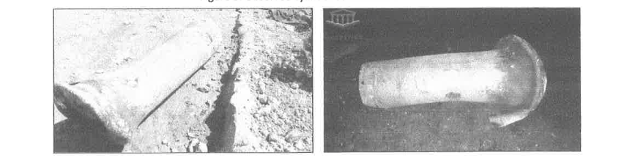
| Figure 8: Cylinder at Location 4 |
Page 12 of 15
UNCLASSIFIED - OPCW Sensitive
Do not circulate
Appendix 4
 |
Figure 9: Location 4 cylinder post-impact superimposed onto crater (baseline configuration, for illustrative purposes). Sketch from a scaled drawing
|
 |
| Figure 10: Location 4 cylinder post-impact superimposed onto crater, from dimensional model |
Page 13 of 15
UNCLASSIFIED - OPCW Sensitive
Do not circulate
Appendix 5
 |
| Figure 11: Test case - nose-down angle of incidence |
 |
| Figure 12: Test case - horizontal angle of incidence |
Page 14 of 15
UNCLASSIFIED - OPCW Sensitive
Do not circulate
 |
| Figure 13: Test case - fin configuration at impact |
 |
| Figure 14: Test case —tail down angle of incidence |
Page 15 of 15
Unfortunately, I couldn't do anything to improve the poor quality of his "professional" illustrations.
Syria is the Paris Commune of the 21st Century!
No comments:
Post a Comment